The Three IWR6843 Evaluation Modules at a Glance
All three modules use the same Texas Instruments IWR6843 60 to 64 GHz mmWave radar SoC. They differ in antenna geometry, mechanical form factor, and intended application. A quick decision tree:
- Need wide field of view, ceiling mount, fast prototype? IWR6843AOPEVM.
- Need a controllable beam pattern for a defined industrial zone? IWR6843ISK.
- Building an occupancy product where elevation matters? IWR6843ODSEVM.
The decision changes the antenna and the mechanical envelope. It does not change the software stack: the mmWave SDK, Code Composer Studio, and UniFlash work identically across the three. A signal-processing chain developed on one EVM ports to the others with minor configuration changes.
Full Specification Comparison Table
| IWR6843AOPEVM | IWR6843ISK | IWR6843ODSEVM | |
|---|---|---|---|
| SoC | IWR6843AOP | IWR6843 | IWR6843AOP |
| Frequency band | 60 to 64 GHz | 60 to 64 GHz | 60 to 64 GHz |
| Antenna | Antenna-on-Package | Etched patch array | Antenna-on-Package, tuned |
| TX / RX channels | 3 TX / 4 RX | 3 TX / 4 RX | 3 TX / 4 RX |
| Azimuth field of view | 120° | 108° | 120° |
| Elevation field of view | 120° | 44° | 120° |
| Typical mounting | Ceiling, overhead, doorway | Wall, fixed-zone, industrial | Ceiling, with elevation rays |
| Best for | People counting, occupancy with wide FoV | Industrial safety, zone monitoring, vehicle exterior | Occupancy detection, fall detection |
| On-board interfaces | USB, 60-pin HD connector | USB, 60-pin HD, LVDS via DCA1000EVM | USB, 60-pin HD connector |
| Form factor | Compact, 65 × 60 mm class | Mid-size, 102 × 67 mm class | Compact, ceiling-suitable |
| Migration to production | Direct, IWR6843AOP package | Direct, IWR6843 package, custom antenna design needed | Direct, IWR6843AOP package |
Notes. Field-of-view numbers are the 6 dB beamwidth from the antenna pattern published in the relevant TI user guide. Always validate the pattern against your specific mounting before committing to a production design. For industrial applications where the radar sits behind a radome or housing, the housing material and thickness materially affect the pattern.
IWR6843AOPEVM in Detail
The IWR6843AOPEVM is the fastest path to a working 60 GHz radar prototype. The IWR6843AOP package has the antennas integrated, which means the EVM and the production PCB use the same antenna pattern. That is rare in radar: most platforms require a substantial antenna re-design when moving from EVM to product.
Where it wins: people counting, doorway monitoring, ceiling-mounted occupancy with a wide field of view, contactless presence detection in care rooms. The 120 by 120 degree pattern is forgiving of mounting variation.
Where it does not win: applications requiring a focused beam to ignore reflections from outside the safety zone. For a forklift presence sensor that must look forward and not sideways, the ISK is the better choice.
IWR6843ISK in Detail
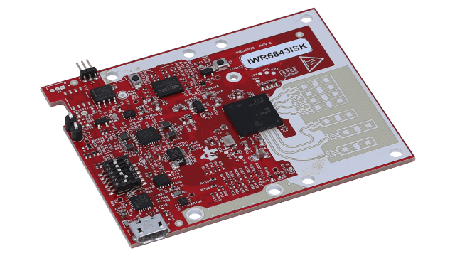
The IWR6843ISK uses an etched patch antenna array on the PCB itself, which gives a narrower elevation beam (around 44 degrees) than the IWR6843AOPEVM. That makes it the right starting point for industrial safety functions where the radar should see only a defined zone and ignore reflections from the floor or from above the target plane.
Where it wins: machine safety radar engineering, vehicle exterior monitoring, AGV obstacle detection. The mechanical form factor is also bigger and has more mounting options.
Where it does not win: any application where antenna-on-package would simplify the production PCB design. The patch antenna on the ISK does not migrate directly to a custom board: you would either need to redesign the antenna for the AOP variant or carry the patch antenna over with care.
IWR6843ODSEVM in Detail
The IWR6843ODSEVM is the antenna-on-package variant tuned for occupancy work. Mechanically and electrically it is close to the IWR6843AOPEVM. The difference is in the reference firmware and the mounting orientation: it is designed to be ceiling-mounted with a defined look-down angle, and the bundled software emphasises people-tracking with elevation information.
Where it wins: smart building occupancy detection with elevation, and as the starting point for contactless fall detection development where vertical motion matters.
Where it does not win: as a generic prototype for radar exploration. The IWR6843AOPEVM is usually a better first board because of better documentation and broader application coverage.
Accessories That Extend the EVMs
Two accessories show up on almost every program.
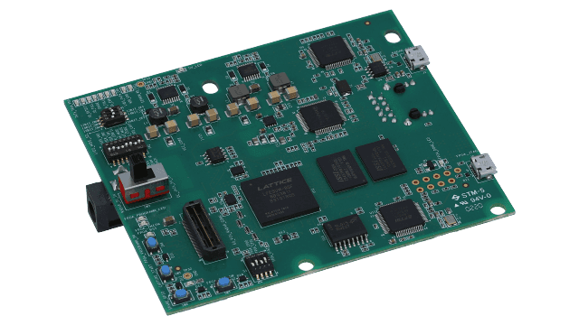
- DCA1000EVM: streams raw ADC samples over LVDS via Ethernet. Essential when developing custom signal-processing algorithms that need to see pre-processed data. Adds about €400 to the bench cost.
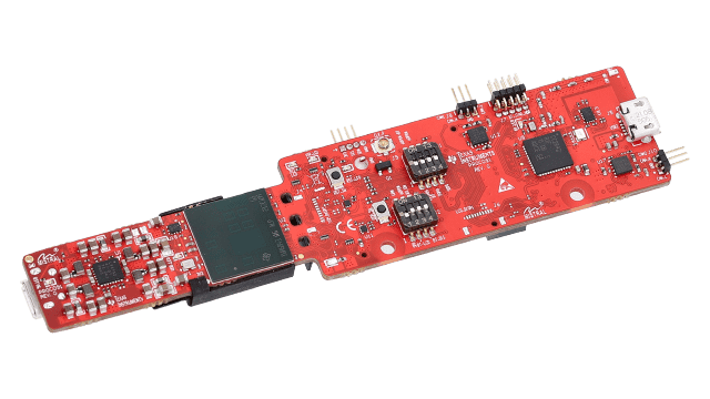
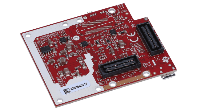
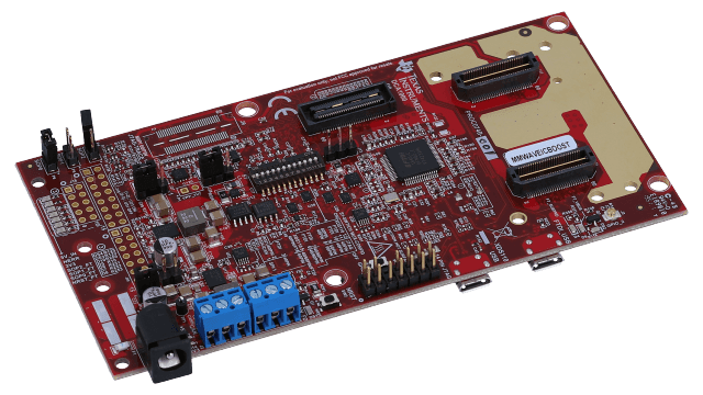
- MMWAVEICBOOST: a carrier card that turns the EVMs into TI BoosterPack-compatible boards. Useful for system-level prototypes where the radar pairs with a TI MCU or processor LaunchPad.
Both are widely available and well-documented. For an enterprise-tier program, plan to spend two to four weeks per engineer becoming familiar with the bench before serious algorithm work starts.
When to Pick Each EVM for Your Application
Pragmatic recommendations from running radar programs across the four application clusters on this site:
- For 60 GHz radar people counting: IWR6843AOPEVM as default. Migrate to IWR6843ODSEVM if elevation matters.
- For mmWave occupancy sensing: IWR6843ODSEVM as default. IWR6843AOPEVM is acceptable when the ceiling is low and the room is small.
- For contactless fall detection development: IWR6843ODSEVM. Vertical motion classification needs elevation data.
- For industrial radar safety sensors: IWR6843ISK. The narrower beam matches the defined-zone requirement of IEC 61496 functions.
Selection is a one-time decision early in the program. The cost of changing it later is a PCB redesign and re-qualification, both substantial. Spending an extra week up front to validate the antenna pattern against the mounting envelope is always worth it.
From Evaluation to Production: Migrating to a Custom PCB
The EVM gets you to a working prototype. The product needs a custom PCB. The migration is a planned, well-understood engineering step.
The work breaks into four parts. Mechanical envelope and stack-up redesign for your housing. Antenna integration, which is straightforward for the AOP variants (the antenna comes with the package) and substantial for the ISK (you redesign or carry over the patch array). Power management, EMC, and certification region adaptation (FCC Part 15.255 in the US, ETSI EN 305 550 in the EU). And finally validation that the production board behaves identically to the EVM on your test suite.
For an enterprise program with safety implications, the production PCB is itself part of the FMEDA and safety lifecycle. Component selection, power island isolation, and EMC shielding all contribute to the dependent-failure analysis. Plan two to three months of focused PCB and FMEDA work between the working prototype and a production-intent board.
Common Mistakes in EVM Selection
- Picking the cheapest EVM first. If your application needs a narrow beam, starting on the IWR6843AOPEVM and discovering at month four that the beam is too wide is more expensive than picking the ISK on day one.
- Skipping the antenna characterisation. Mount the radar on a representative mechanical mock-up before tuning algorithms. Mounting plates, housings, and nearby reflective surfaces all affect the pattern.
- Underestimating the SDK learning curve. The mmWave SDK is well-documented but assumes prior radar signal-processing knowledge. Budget three to four engineer-weeks for proficiency.
- Building production firmware on the EVM debug toolchain. The EVM tools are not the production tools. Switch to a version-controlled, qualified toolchain early.
Frequently Asked Questions
What is the difference between IWR6843AOPEVM and IWR6843ISK?
The IWR6843AOPEVM uses antenna-on-package with a 120 by 120 degree field of view, ideal for ceiling-mount applications. The IWR6843ISK uses a patch-antenna array with a narrower beam, tuned for industrial scenes with a defined target zone. Both share the same IWR6843 SoC and run the same mmWave SDK, so software developed on one ports to the other.
Which TI mmWave EVM is best for occupancy detection?
The IWR6843ODSEVM is purpose-tuned for occupancy detection with elevation. The IWR6843AOPEVM is a strong alternative when ceiling mount and a wide field of view are needed without elevation. For an in-room sensor mounted above a doorway, the IWR6843AOPEVM is usually sufficient and cheaper.
Can the IWR6843AOPEVM be used in production?
In small volumes and pilots, yes. Most enterprise programs migrate to a custom PCB before mass production, for reasons of mechanical envelope, cost, certification region, and BOM control. The migration uses the same IWR6843AOP package, so software developed on the EVM ports cleanly.
What software do I need for the IWR6843AOPEVM?
Code Composer Studio for development, the mmWave SDK for the radar firmware, mmWave Studio for low-level data capture and debugging, and UniFlash for programming. All are free downloads from Texas Instruments. Most production projects also use a third-party DSP library and custom signal-processing code on top.
How do I migrate from the IWR6843AOPEVM to a custom PCB?
Three steps. First, qualify the algorithm and antenna pattern on the EVM. Second, design a custom PCB with the same IWR6843AOP package, your specific mechanical envelope, and any region-specific power and antenna modifications. Third, port the firmware (essentially unchanged) and re-run validation against your safety and EMC requirements.
Get help choosing the right EVM
Thirty-minute call with our principal engineer to match the right module to your mounting, beam pattern, and certification region.

Lukas Hofstätter
Founder and Managing Director, HALready GmbH
Lukas has led 60 GHz mmWave radar programs across all three IWR6843 evaluation modules, with field deployments in industrial, smart-building, and medical applications. He oversees radar selection and architecture for HALready engagements at Bosch, Vorwerk, and confidential industrial OEMs.